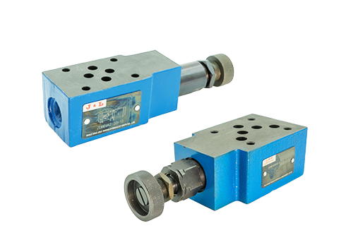
2025-10-22 The installation of the stacked relief valve must follow a standardized process, combined with the design requirements of the hydraulic system, and ensure its stable performance through standardized operations. The following are the specific installation methods and key steps: 1. Prepare the environment and tools before installation to ensure that the installation environment is dry, dust-free, and well-ventilated to prevent impurities from entering the hydraulic system. Prepare tools such as wrenches, screwdrivers, seals, pipes, etc. and check their integrity. Component inspection: Check whether the certificate of qualification, operating instructions and spare parts of the stacked relief valve are complete. Confirm that the valve body has no packaging damage or foreign matter, the oil port has not been opened, and all components are tightly connected without leakage. Clean the valve body and connecting parts with kerosene to remove oil dirt and impurities. System matching confirms that the model, diameter and parameters (such as pressure regulating range) of the superimposed relief valve are consistent with the hydraulic system design requirements. Check the cleanliness of the hydraulic oil. Contamination particles must meet ISO 4406 grade requirements (usually ≤18/16/13). 2. Basics of installation sequence and steps
Read More 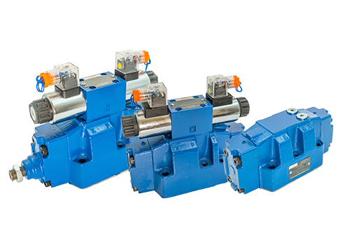
2025-10-18 The maintenance of the 4WEH16 electro-hydraulic reversing valve needs to start from various aspects such as installation, hydraulic system, electrical connection, sealing fastening, safety protection and daily use. The details are as follows: Installation and location: The electro-hydraulic reversing valve should be installed on the connecting base plate using the specified screws. Pipes are not allowed to support the valve. During installation, the axis must be kept horizontal, and tilted and vertical installations are not allowed to ensure normal operation. The surface roughness of the joint surface between the base plate and the valve should be guaranteed to be within a certain range, and the flatness should be less than 0.1mm to ensure sealing performance. Hydraulic system maintenance: Hydraulic oil selection: Hydraulic oil must be selected strictly in accordance with the standards and parameters specified by the manufacturer, and must undergo rigorous filtration tests with a filtration accuracy of at least 20 μm to ensure that the hydraulic valve can operate normally. If there are impurities in the hydraulic system, it will affect the life of the reversing valve and even cause damage. Liquid level inspection: Pay attention to the inspection and control of the liquid level. When the working fluid of the reversing valve
Read More 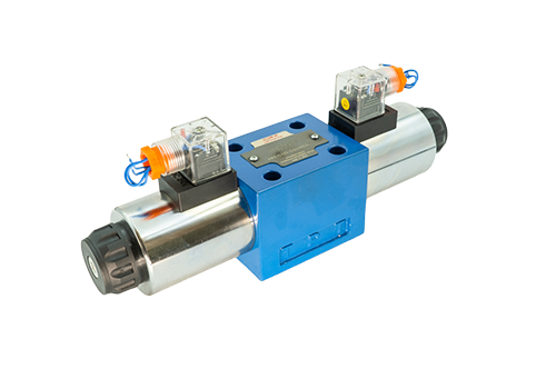
2025-10-16 Precautions for the use of the 4WE10 solenoid directional valve are as follows: 1. Installation and connection Installation direction The axis of the solenoid directional valve must be installed in the horizontal direction. Vertical installation may cause the valve core, armature and other parts to reverse or reset abnormally due to the influence of gravity. The connection method should be coordinated with the installation and connection methods of other hydraulic valves in the hydraulic system, and the appropriate installation and connection method should be selected. For electromagnetic reversing valves with plate-type connection, O-rings must be used to seal each oil port and the installation base plate. The surface of the base plate should be ground and processed to ensure flatness to avoid oil leakage. When installing the fixing screws, the fixed connection screws should be evenly stressed to prevent the valve body from deforming or the valve core from being stuck. 2. The matching voltage of the electrical control power supply must be consistent with the coil voltage to avoid coil burnout. Electromagnets are divided into DC and AC, and the appropriate model needs to be selected according to the control power supply parameters. Interlocking design The two electromagnets of the double-solenoid solenoid valve cannot be energized at the same time. When designing the electronic control system of hydraulic equipment, the action of the two electromagnets should be
Read More 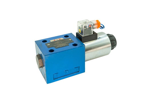
2025-10-10 The characteristics of the 4WE10 single-head solenoid directional valve are as follows: heavy-duty design and high pressure resistance. The 4WE10 series adopts a heavy-duty design, with a larger valve core diameter, a working flow of up to 320L/min, a rated pressure of 31MPa, and a maximum pressure of 35MPa. It is suitable for heavy-duty machinery and equipment such as ships and injection molding machines. Its structure is standardized, durable and reliable, and complies with DIN24340 and ISO 4401 standards to ensure stable operation in high-pressure environments. Principle of combination of direct-acting and pilot-operated direct-acting: when the power is on, the electromagnetic coil generates electromagnetic force, which directly lifts the closing member to open the valve; when the power is off, the spring presses back the closing member to close the valve. It is suitable for small diameter, low pressure or vacuum conditions, with fast response speed, short action time and high opening and closing frequency. Pilot type: When the power is turned on, the electromagnetic force opens the pilot hole, forming a pressure difference to push the closing member of the main valve to move; when the power is turned off, the spring force or medium pressure pushes the closing member to reset. Suitable for high pressure difference or large flow scenarios
Read More 2025-10-07 Stacked relief valve: full analysis of principles, adjustments and maintenance. As the core control component in the hydraulic system, the stacked relief valve assumes the important responsibility of stabilizing system pressure and ensuring the safe operation of equipment. With its unique structural design and flexible adjustment method, it has been widely used in industrial automation, construction machinery and other fields. This article will start from the basic concepts and systematically explain its adjustment methods and maintenance points to help readers deeply master this key technology. 1. The core characteristics of the stacked relief valve The stacked relief valve adopts a modular design concept and consists of a main valve core assembly and a stacked installation valve block. Its working principle is based on the pressure balance theory in fluid mechanics, and it controls the pressure and flow in the hydraulic system by adjusting the valve opening. When the system pressure exceeds the set value, the valve core automatically opens and leads excess hydraulic oil back to the tank to maintain system pressure stability. This design not only simplifies the hydraulic pipeline layout, but also realizes pressure control.
Read More 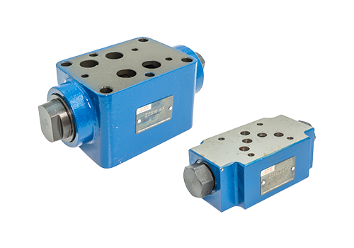
2025-09-30 As a key component in the hydraulic system, the superimposed hydraulic control check valve has attracted much attention. The following is a detailed analysis of this hydraulic component: Working principle of superimposed hydraulic control check valve. Although the core working principle of superimposed hydraulic control check valve is similar to that of conventional hydraulic valves, it is the same in structural design and connection size, forming a standardized series. It not only has the control function of traditional hydraulic components, but also plays the role of oil passage. The layout of the main oil passage and bolt connection holes of each diameter series are consistent with the reversing valves of the same specifications, thus supporting flexible superposition and building a hydraulic control system with diverse functions. The valve is mainly composed of a solid steel valve body, one or two check valves, a pilot stage piston and a pilot cone valve spool embedded in the main valve spool of the check valve. When the oil flows from port A1 to port A2, the check valve (2) opens while pushing the pilot piston.
Read More 


