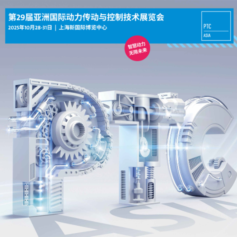
2025-11-07 From October 28th to 31st, 2025, the 29th Asian International Power Transmission and Control Technology Exhibition (PTC ASIA) opened grandly at the Shanghai New International Expo Center. As a benchmark event for the power transmission industry in the Asia-Pacific region, this exhibition brings toge
Read More 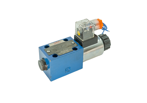
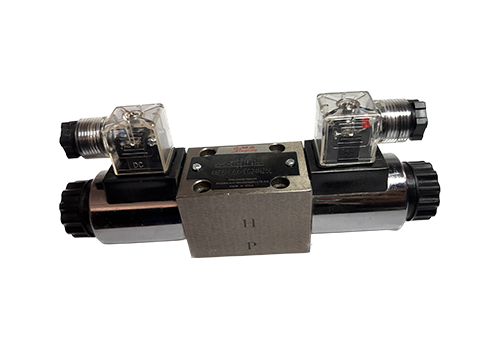
2026-03-23 Common faults of single-head electromagnetic reversing valves mainly include unreliable commutation, coil failure, leakage problems, shock and vibration, and installation and assembly problems, as follows: Unreliable commutation or inability to commutate: Electromagnet problems: Burned out electromagnet coil, insufficient electromagnet driving force or magnetic leakage, electrical circuit failure, etc., may cause the electromagnet to fail to work properly, thereby affecting commutation. For example, a coil short circuit or open circuit may be caused by coil quality problems, excessive power supply voltage, repeated shocks, or excessive mechanical vibration. Pilot solenoid valve failure: the valve core and valve body hole are stuck, the spring is bent sideways, etc., which may also lead to unreliable commutation. This is usually caused by poor geometric accuracy of the parts, tight fit between the valve core and the valve hole, or excessively dirty oil. The main valve core is stuck: The geometric accuracy of the valve core and the valve body is poor, the valve core and the valve hole are too tight, there are burrs on the valve core surface, or there is no oil in the control oil line, etc., which may cause the main valve core to be stuck, thus affecting the direction change. Other factors: if
Read More 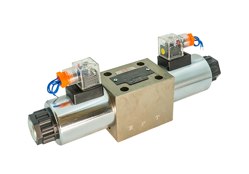
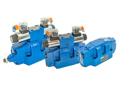
2026-03-21 The working principle of 4WE10 high-pressure solenoid directional valve is as follows: Basic structure: 4WE10 high-pressure solenoid directional valve is mainly composed of valve body, valve core, electromagnet and return spring. There are multiple oil ports in the valve body, and the valve core can move in the valve body to change the connection status of the oil ports. Electromagnetic control: energized state: When the electromagnet is energized, electromagnetic force is generated to attract the valve core to move, overcome the resistance of the return spring, and make the valve core reach the designated position. At this time, specific oil ports are connected, and hydraulic oil can flow through these ports, thereby changing the direction of the oil path of the hydraulic system. Power-off state: When the electromagnet is powered off, the electromagnetic force disappears, and the return spring pushes the valve core back to its initial position, closing the previously connected oil port and restoring the valve's initial state. Oil circuit switching: By controlling the power on and off of the electromagnet, the valve core moves back and forth in the valve body to achieve switching between different oil ports and control the flow direction of hydraulic oil. This makes the actuators in the hydraulic system (such as hydraulic cylinders
Read More