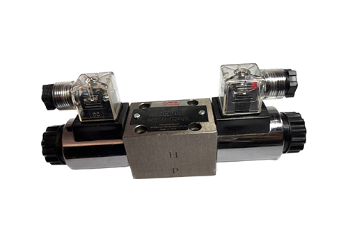
2026-01-22 As a key control component in industrial hydraulic systems, 4WE6 high-pressure solenoid directional valve has significant advantages such as high pressure and flow adaptability, fast response and long life, high compatibility and stability, flexible control method, structural optimization and convenient maintenance. The details are as follows: 1. High pressure and flow adaptability High rated working pressure: The rated working pressure of the 4WE6 series solenoid valve can reach 31.5MPa (some models are even higher, such as 350bar), which can easily meet the needs of high-pressure hydraulic systems. Wide flow range: The flow range is between 10-25L/min (there are slight differences in different specific models). The maximum flow capacity of some models can reach 80L/min, which meets the control requirements of large-flow hydraulic systems. 2. Fast response and long life. Fast response: the reversing time only takes tens of milliseconds, which enables the hydraulic actuator to move quickly, greatly improving the working efficiency of the system. use
Read More 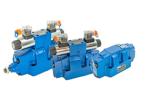
2026-01-19 The maintenance methods of 4WEH16 electro-hydraulic directional valve are as follows: Routine appearance and connection inspection: Check the valve body, valve cover, flange connection: Check whether there are signs of leakage, such as oil stains, water stains, rust spots, etc. If leakage is found, the connecting parts need to be tightened or the seals replaced in time. Observe the anti-corrosion layer on the surface of the valve: Check whether the anti-corrosion layer has fallen off. If it does, it should be repainted in time to prevent rust and corrosion of the valve body. Remove oil and dust from the valve surface: especially clean the valve stem and sealing parts to prevent impurities from invading the sealing surface and affecting the sealing performance. Can be wiped with a clean soft cloth or special detergent. Maintenance of the valve stem and transmission mechanism: Add designated grease: According to equipment requirements, add designated grease, such as lithium-based grease, high-temperature grease, etc., to the valve stem and transmission mechanism to avoid dry friction, reduce wear, and extend service life. Regular manual opening and closing: For normally open or normally closed 4WEH16 electro-hydraulic directional valve, regular manual opening and closing 1 - 2 times
Read More 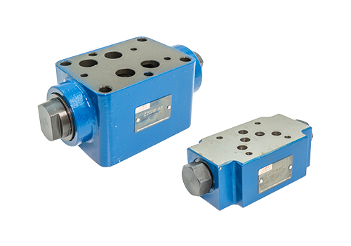
2026-01-16 As a key control component in the hydraulic system, the superimposed hydraulic control check valve has various types of faults and has a significant impact on system performance. The following are common faults of superimposed hydraulic control check valves and their detailed analysis: 1. Leakage failure, aging and wear of the sealing ring or sealing surface: After long-term use, the sealing ring may lose elasticity due to aging, or the sealing may be lax due to wear and tear, causing hydraulic oil leakage. Wear of the valve core and valve seat: Frequent contact and relative movement between the valve core and valve seat may cause wear, thereby destroying the sealing and causing leakage. Dirt or burrs: Dirt in the hydraulic oil or burrs on the valve core and valve seat may scratch the sealing surface and cause leakage. Solution: Replace the sealing ring or sealing surface, clean or replace the damaged valve core and valve seat components, and ensure the cleanliness of the hydraulic oil. 2. Stuck failure Valve core and valve seat wear: In addition to causing leakage, wear may also cause the valve core to get stuck in the valve seat and unable to move normally. Dirt or burrs: dirt
Read More 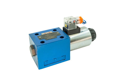
2026-01-08 The wiring of a single-head solenoid reversing valve needs to be distinguished according to the power supply type (DC or AC) and the wiring method (lead type or junction box type). The following are the specific steps and precautions: 1. Wire the DC power supply (such as DC24V) according to the power supply type. Lead type solenoid valve: There are usually three wires, namely positive, negative and ground wires. Positive pole: Connect to the positive pole of the DC power supply (such as DC24V+). Negative pole: Connect to the negative pole of the DC power supply (such as DC24V-). Ground wire: Connect to the equipment shell or system ground terminal to ensure safety. Junction box type solenoid valve: There are usually three terminals in the junction box, which are the power terminal (regardless of positive and negative poles) and the ground terminal. Connect any end of the power cord (such as DC24V) to the power terminal, and the other end to the other power terminal. The ground wire is connected to the ground terminal. AC power supply (such as AC220V) lead-type solenoid valve: the three wires are live wire, neutral wire and ground wire. Live wire: connected to AC power
Read More 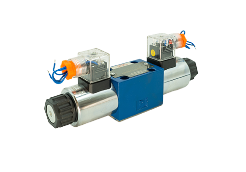
2025-12-30 The function of the electrical end of the electromagnetic reversing valve is to attract the valve core. Its working principle and process are as follows: Working Principle The electromagnetic reversing valve is mainly composed of a valve body, a valve core, an electromagnet and a spring. Its working principle is based on the interaction between the magnetic force generated when the electromagnet is energized and the spring force, and the fluid channel is changed by controlling the movement of the valve core to achieve the reversing function. The energized state during the action process of the electrified end: When the electromagnet at one end of the electromagnetic reversing valve is energized, the electromagnet generates magnetic force. This magnetic force will attract the valve core, causing the valve core to move in the direction of the electromagnet (that is, the direction of attraction) against the spring force. As the valve core moves, the fluid channel is switched to the corresponding position, thereby realizing fluid reversal. Power-off state: When the electromagnet is powered off, the electromagnetic force disappears. At this point, the spring force comes into play, pushing the valve core back to its original position. The reset of the valve core restores the initial fluid passage and prepares for the next change of direction. Performance of the pull-in action in practical applications: in solenoid directional valves
Read More 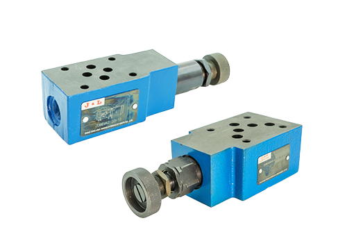
2025-12-27 As a pilot hydraulic control component, the ZDB10V superimposed relief valve has the characteristics of modular design, precise pressure regulation, adaptability to high pressure and large flow, flexible adjustment method, anti-corrosion design, stability and reliability, convenient installation and wide application. The details are as follows: Modular superimposed structure: The superimposed valve plate design is used to facilitate installation in combination with other hydraulic valves, reduce system complexity and leakage points, and improve overall reliability. Precise pressure control: The pilot valve and main valve work together to achieve high-precision pressure regulation to ensure system pressure stability and avoid pressure fluctuations from impacting the equipment. High-pressure and large-flow adaptability: The working pressure can reach 315 bar and the flow rate can reach 100 L/min. It is suitable for high-pressure and large-flow hydraulic systems to meet the needs of high-load working conditions. Flexible adjustment methods: Provides various adjustment modes such as knobs, hexagonal sleeves, and lockable knobs with scales, which are easy to operate and meet the pressure adjustment needs of different scenarios. Anti-corrosion design
Read More 


