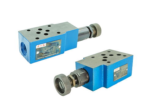
2026-03-19 As a pilot pressure control valve, the ZDB10V superimposed relief valve achieves multi-stage pressure regulation and stable control through modular design. It is widely used in engineering machinery, industrial equipment, shipbuilding, automation equipment, hydraulic testing systems and other fields. The following is its specific application scope and technical advantages: 1. Typical equipment in core application fields of engineering machinery: hydraulic circuits such as excavators, cranes, loaders, etc. Function: As the main safety valve to prevent system overpressure, it also adapts to different working conditions (such as excavation, walking, and lifting) through multi-stage pressure adjustment. Advantages: The superimposed structure saves installation space, responds quickly to pressure changes, and avoids equipment damage due to pressure shock. Typical equipment for industrial automation equipment: injection molding machines, die-casting machines, hydraulic presses and other precision manufacturing equipment. Function: Provide stable pressure during mold closing, injection, pressure holding and other stages to ensure product molding quality. Advantages: Supports multi-level pressure switching, adapts to complex process flows, and reduces energy loss.
Read More 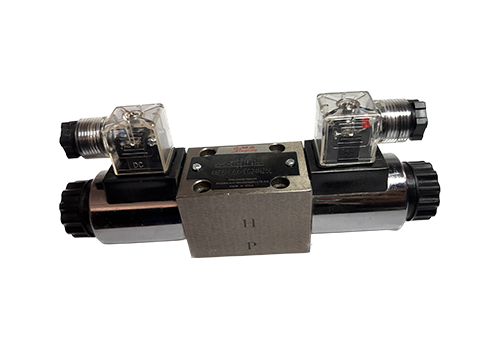
2026-03-17 The 4WE6 high-pressure electromagnetic reversing valve is the core direction control component in the hydraulic system. Its core function is to realize the switching, on-off control and reversal function of liquid flow through electromagnet control, thereby driving hydraulic actuators (such as hydraulic cylinders and hydraulic motors) to complete precise actions. The following is a detailed description of its specific functions and technical characteristics: 1. The core function of flow direction switching and on-off control is to energize or de-energize the electromagnet to drive the valve core to move in the valve body and change the liquid flow path. For example: switching the liquid from the oil inlet (P port) to the working oil port (A port or B port), driving the hydraulic cylinder to extend or retract; blocking the oil flow (neutral function), keeping the hydraulic cylinder in a stationary or locked position. In a double-acting hydraulic cylinder, the reciprocating motion of the piston (such as telescopic, lifting, rotating, etc.) is achieved by alternately switching the energized state of the electromagnet. System safety protection: When the system pressure exceeds the set value, the electromagnetic reversing valve can automatically open the overflow channel to prevent
Read More 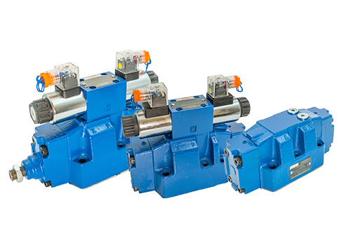
2026-03-11 As a spool-type directional valve controlled by a solenoid valve as a pilot, the 4WEH16 electro-hydraulic directional valve has a series of significant characteristics. The following is a detailed introduction in five aspects: structure, performance, control method, additional devices and application areas: 1. Structural characteristics Plate connection: The 4WEH16 electro-hydraulic directional valve adopts a plate connection, and its connection dimensions comply with DIN24340A and ISO4401 standards, making it easy to install and replace. Core components: The valve is mainly composed of a main valve body, a main valve core, one or two return springs, and a pilot solenoid valve with one or two electromagnets. The main valve core is held in the middle position by spring force or hydraulic pressure, and the pilot solenoid valve controls the direction of the main valve. 2. Performance characteristics and high reliability: 4WEH16 electro-hydraulic directional valve has high reliability and can work stably under various harsh working conditions. Fast reversing response: The valve has fast reversing response and sensitive response, which can meet the needs of high-speed automated production lines.
Read More 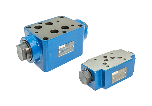
2026-03-09 The superimposed hydraulic control check valve itself does not have the active adjustment function of flow or pressure, but it can indirectly achieve the adjustment effect through system design. Its core function is to control the unidirectional flow of oil and allow reverse flow under certain conditions, rather than directly adjusting flow or pressure parameters. The following is a specific analysis: The core function of the superimposed hydraulic control check valve is one-way cut-off: ensuring that oil can only flow in one direction, and is blocked in the opposite direction to avoid reverse flow or backflow. Hydraulic control opening: By introducing external control oil pressure, the reverse cutoff can be actively opened to allow reverse flow of oil. How to realize the adjustment function Although the superimposed hydraulic control check valve itself does not have the adjustment function, it can indirectly achieve the adjustment effect in the following ways: Use in combination with a regulating valve: In the hydraulic system, the superimposed hydraulic control check valve can be used in combination with other regulating valves (such as relief valves, throttle valves, etc.) to indirectly affect the work of the superimposed hydraulic control check valve by adjusting the parameters of other valves.
Read More 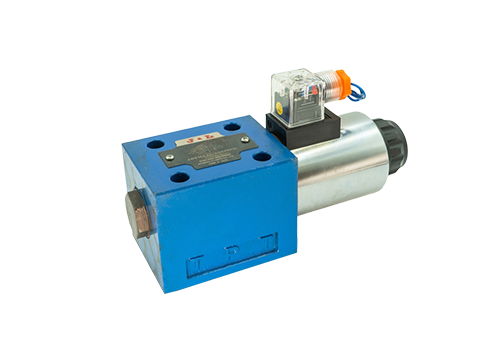
2026-03-06 The wire connection of the single-head solenoid directional valve needs to be operated according to its voltage type (DC or AC) and specific terminals. The following are detailed steps and precautions: 1. Prepare to confirm the voltage type before wiring. Direct current (DC) solenoid valve: It is necessary to distinguish the positive and negative poles (usually marked '+' and '-'). Reverse connection may cause non-operation or damage. AC solenoid valve: No need to distinguish polarity, live and neutral wires can be connected arbitrarily. Check the voltage value: Make sure the power supply voltage is consistent with the rated voltage of the solenoid valve (such as 24V DC, 220V AC, etc.). Identify the wiring terminal of the two-wire solenoid valve: usually the power wire (positive/live wire, negative/neutral wire), some with grounding terminal (yellow and green two-color wire). Three-wire solenoid valve: may include common terminal (COM), normally open terminal (NO), normally closed terminal (NC), which need to be connected according to the control logic. Solenoid valve with indicator light: The indicator light wire must be connected according to polarity, otherwise it will not light up but will not affect the function.
Read More 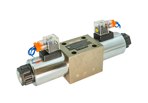
2026-03-03 1. Basic structure and working principle 4WE10 high-pressure solenoid directional valve is mainly composed of valve body, electromagnet, control valve core and return spring. Its working principle is based on the action of electromagnetic force: In the power-off state: the control valve core is held in the intermediate position or initial position by the return spring (depending on the functional type of the valve, such as the 'O' type functional valve core is in the middle closed state). At this time, the oil inlet chamber is not connected with the working oil chamber and the oil return chamber, and the system is in a static state. Energized state: When the electromagnet is energized, a magnetic field is generated to attract the control valve core to move to the required end position. According to different combinations of electromagnet energization, the following functions can be achieved: Single electromagnet energization: the control valve core moves to one side so that the oil inlet chamber is connected to a certain working oil chamber, and the other working oil chamber is connected to the oil return chamber, thereby driving the hydraulic actuator (such as a hydraulic cylinder or hydraulic motor) to move in one direction. The other electromagnet is energized: the control valve core moves in the reverse direction and changes the flow rate of the working oil chamber.
Read More 


