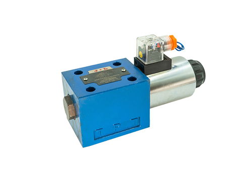
2025-12-16 The single-head electromagnetic directional valve controls the movement of the valve core through electromagnetic force to control the flow direction, flow rate, speed and other parameters of the fluid in the hydraulic system. Its working principle and control method are as follows: Working principle and basic structure: The single-head electromagnetic directional valve is mainly composed of valve body, valve core, spring, armature and solenoid coil. There is a closed cavity in the valve body. According to actual needs, holes are opened in different positions of the cavity to communicate with the outside. Each hole will be connected to the corresponding pipeline. A valve core is installed in the middle of the cavity. The valve core and the armature are integrated, and an electromagnet and a spring are installed on each side. Electromagnetic control: When the electromagnet is energized, it will generate a certain electromagnetic force. When this electromagnetic force exceeds the elastic force of the spring, it will attract the valve core and control the opening or closing of the external hole through the movement of the valve core. When the solenoid coil is powered on and off, the valve core will move left and right, and the spring will act as a buffer to prevent the valve core from exerting too much force on the valve body.
Read More 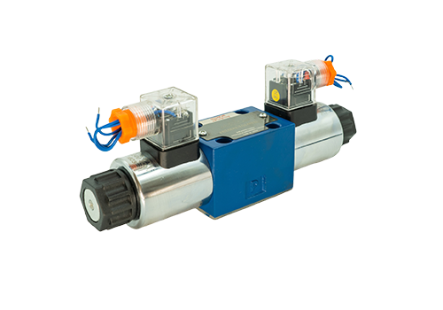
2025-12-13 The four holes (P, T, A, B) of the solenoid directional valve themselves do not involve the distinction between positive and negative poles. Their function is to control the flow direction of the fluid, not the direction of the current. The following is a detailed explanation: The function of the four holes of the solenoid reversing valve is P port (pressure oil source): connected to the outlet of the hydraulic pump to provide pressure oil for the system. T port (tank return): connected to the fuel tank for oil return. Port A and Port B: are respectively connected to the actuator (such as the two chambers of the hydraulic cylinder), and the oil circuit is switched on and off and the flow direction is changed through the valve core switching. The working principle of the electromagnetic reversing valve is that the electromagnetic reversing valve drives the displacement of the valve core through the electromagnet, switches the direction of the oil circuit, and thereby controls the movement direction of the actuator such as the hydraulic cylinder or motor. For example, when the electromagnet is energized, the valve core moves to make P→A, B→T, and the actuator moves in the forward direction; otherwise, P→B, A→T, and the actuator moves in the reverse direction. The relationship between the electromagnetic reversing valve and the positive and negative poles. The electromagnet part: The electromagnet part of the electromagnetic reversing valve may involve
Read More 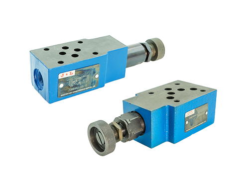
2025-12-11 To adjust the pressure of the superimposed relief valve, the core is to turn the adjusting screw clockwise to increase the pressure and turn it counterclockwise to decrease the pressure. Be sure to perform the operation in stages and tighten the nut. The specific steps are as follows: Loosen the lock nut: Find the lock nut on the valve body and use a wrench to loosen it to prepare for adjustment. Adjust pressure: Use a wrench to hold the adjusting screw. Turn clockwise (tightening) to gradually increase the system pressure, and turn counterclockwise (loosen) to reduce the pressure. It is recommended to rotate 1/4 turn for each adjustment, then observe the pressure gauge reading, and wait for the pressure to stabilize before proceeding to the next step. Lock Nut: After the pressure is adjusted to the required value, use a wrench to retighten the lock nut to fix the position of the adjusting screw to prevent pressure fluctuations. Key notes: Step-by-step pressure increase: Do not adjust the pressure to the target value all at once. Adjust it step by step multiple times and allow the system to run stably for a few minutes after each adjustment. Use a torque wrench
Read More 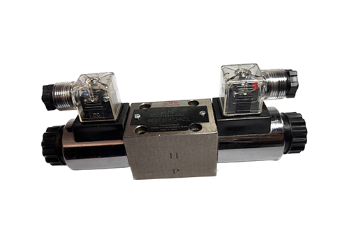
2025-12-06 The characteristics of the 4WE6 high-voltage solenoid reversing valve are as follows: The structure and driving method adopts a direct-acting reversing slide valve structure, driven by a wet AC or DC electromagnet. The interior of the electromagnet is fully enclosed and insulated, and the armature moves in the oil. This design significantly reduces mechanical wear, reduces impact, and improves heat dissipation efficiency, thereby extending the reliability and service life of the commutation and reset actions. Flow Capacity and Pressure Characteristics The cast internal channel design effectively reduces pressure loss, and the maximum flow capacity can reach 80L/min, which is nearly twice that of domestic valves of the same diameter. The nominal pressure range covers 25MPa to 350bar, which can adapt to high-pressure working conditions and ensure stable operation in harsh environments. The control function and spool valve function supports a variety of spool valve function configurations such as three-position four-way, two-position four-way, or two-position three-way, and provides 53 standard function options to meet the diverse control needs of complex hydraulic systems. When the electromagnet is energized, it pushes the valve core to switch the oil circuit, and resets when the power is turned off.
Read More 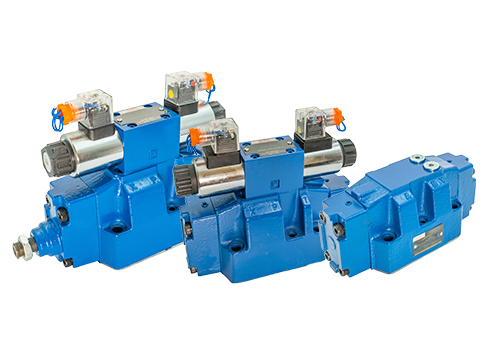
2025-12-04 Installation steps and precautions for the 4WEH16 electro-hydraulic directional valve 1. Basic preparation of the installation steps and component inspection to confirm the integrity of the equipment: Check whether the valve body, main valve core, return spring, pilot solenoid valve (including electromagnet), seals and other components of the 4WEH16 electro-hydraulic directional valve are complete, and check whether the model and specifications match. Clean the installation environment: Make sure the installation site is flat and free of debris to avoid vibration or impact that affects the stability of the equipment. Check the hydraulic system: Confirm that the cleanliness of the hydraulic oil meets the requirements (filtration accuracy is at least 20 μm) to avoid impurities entering the valve body and causing wear or stuck. Main structure installation installation method selection: Horizontal installation is preferred: the axis of the valve body should be kept horizontal and avoid tilted or vertical installation (unless the model explicitly allows it). Fixing of the connecting base plate: Use the specified screws to fix the valve body on the connecting base plate, ensuring that the roughness of the joint surface is ≤ Ra0.8 and the flatness is ≤ 0.01mm/100mm to prevent oil leakage or vibration.
Read More 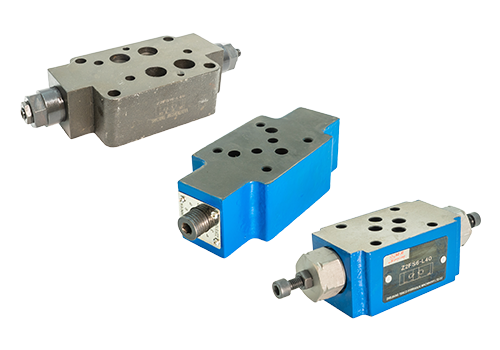
2025-12-01 Maintenance tips and suggestions for superimposed hydraulic control check valves 1. Daily inspection and cleaning Regular inspection: Regularly inspect the superimposed hydraulic control check valve, focusing on the status of seals, control pistons, springs and other wearing parts. Check whether the valve is stuck and ensure that the valve can operate normally. Cleaning and maintenance: Regularly clean and maintain the superimposed hydraulic control one-way valve to remove impurities and scale to prevent component wear and sticking. During the cleaning process, special attention should be paid to the protection of precision components such as control pistons and springs to avoid damage. When cleaning, special cleaning agents for hydraulic systems should be used, and corrosive, toxic or flammable cleaning agents should be avoided. 2. Part replacement and adjustment Timely replacement of wearing parts: If problems such as seal aging or damage, control piston wear, spring fatigue or breakage are found, the corresponding parts should be replaced in time. When replacing parts, you should ensure that the quality of the new parts meets the equipment requirements and avoid using inferior or substandard parts. Tuning Parameters: Root
Read More 


