2026-01-16 As a key control component in the hydraulic system, the superimposed hydraulic control check valve has various types of faults and has a significant impact on system performance. The following are common faults of superimposed hydraulic control check valves and their detailed analysis: 1. Leakage failure, aging and wear of the sealing ring or sealing surface: After long-term use, the sealing ring may lose elasticity due to aging, or the sealing may be lax due to wear and tear, causing hydraulic oil leakage. Wear of the valve core and valve seat: Frequent contact and relative movement between the valve core and valve seat may cause wear, thereby destroying the sealing and causing leakage. Dirt or burrs: Dirt in the hydraulic oil or burrs on the valve core and valve seat may scratch the sealing surface and cause leakage. Solution: Replace the sealing ring or sealing surface, clean or replace the damaged valve core and valve seat components, and ensure the cleanliness of the hydraulic oil. 2. Stuck failure Valve core and valve seat wear: In addition to causing leakage, wear may also cause the valve core to get stuck in the valve seat and unable to move normally. Dirt or burrs: dirt
Read More 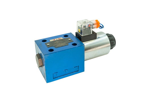
2026-01-08 The wiring of a single-head solenoid reversing valve needs to be distinguished according to the power supply type (DC or AC) and the wiring method (lead type or junction box type). The following are the specific steps and precautions: 1. Wire the DC power supply (such as DC24V) according to the power supply type. Lead type solenoid valve: There are usually three wires, namely positive, negative and ground wires. Positive pole: Connect to the positive pole of the DC power supply (such as DC24V+). Negative pole: Connect to the negative pole of the DC power supply (such as DC24V-). Ground wire: Connect to the equipment shell or system ground terminal to ensure safety. Junction box type solenoid valve: There are usually three terminals in the junction box, which are the power terminal (regardless of positive and negative poles) and the ground terminal. Connect any end of the power cord (such as DC24V) to the power terminal, and the other end to the other power terminal. The ground wire is connected to the ground terminal. AC power supply (such as AC220V) lead-type solenoid valve: the three wires are live wire, neutral wire and ground wire. Live wire: connected to AC power
Read More 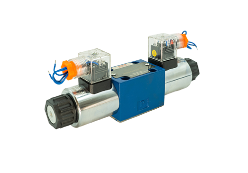
2025-12-30 The function of the electrical end of the electromagnetic reversing valve is to attract the valve core. Its working principle and process are as follows: Working Principle The electromagnetic reversing valve is mainly composed of a valve body, a valve core, an electromagnet and a spring. Its working principle is based on the interaction between the magnetic force generated when the electromagnet is energized and the spring force, and the fluid channel is changed by controlling the movement of the valve core to achieve the reversing function. The energized state during the action process of the electrified end: When the electromagnet at one end of the electromagnetic reversing valve is energized, the electromagnet generates magnetic force. This magnetic force will attract the valve core, causing the valve core to move in the direction of the electromagnet (that is, the direction of attraction) against the spring force. As the valve core moves, the fluid channel is switched to the corresponding position, thereby realizing fluid reversal. Power-off state: When the electromagnet is powered off, the electromagnetic force disappears. At this point, the spring force comes into play, pushing the valve core back to its original position. The reset of the valve core restores the initial fluid passage and prepares for the next change of direction. Performance of the pull-in action in practical applications: in solenoid directional valves
Read More 
2025-12-25 The usage method of 4WE6 high-pressure solenoid directional valve is as follows: 1. Before installation, prepare to check the solenoid valve to confirm that there is no damage to the appearance (such as shell rupture, coil damage), and the model specifications are consistent with the design requirements, including working pressure, flow, voltage and other parameters. Check the nameplate parameters (such as nominal pressure, diameter, voltage type) to ensure they match the actual working conditions. Clean the pipes: Clean the inside of the connecting pipes to remove impurities, rust, welding slag and other foreign matter to prevent the valve core from jamming or loose sealing. It is recommended to flush the pipeline under 0.3MPa pressure to ensure the purity of the medium. Choose an installation location that is dry, well-ventilated, and convenient for operation and maintenance. Avoid strong vibrations, shocks, or close to heat sources, and stay away from low recesses in pipes and container discharge pipes. If the medium may cause water hammer, you need to select a model with waterproof hammer function or take preventive measures. 2. Installation steps: Determine the installation direction strictly according to the medium flow direction marked on the valve body (usually marked with an arrow or '→'
Read More 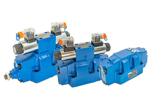
2025-12-22 The disassembly and assembly steps of the 4WEH16 electro-hydraulic reversing valve are as follows: 1. Disassembly steps Preparation work Ensure that the equipment is in a shutdown state, release system pressure, and prevent hydraulic oil from splashing. Prepare tools: Allen wrench, screw driver, kerosene or diesel, clean container, copper rod (steel/iron rod is prohibited), recording tools (such as notebook, camera). Disassemble the electromagnet part and remove the electromagnet coil: Use an Allen wrench to loosen the locking nuts at both ends of the electromagnet coil and gently take out the coil. Take out the spring and push rod: use a screwdriver to gently pry the joint surface, take out the spring, push rod and other small parts, and note their position and direction. Separate the pilot solenoid valve: Loosen the four screws fixing the pilot solenoid valve and remove it from the hydraulic directional valve to become two parts. Disassemble the main valve part and take out the main valve core: remove the main valve core from the valve body and pay attention to the assembly direction of the valve core (cannot be installed upside down, it is directional). Disassemble other parts: take out the positioning sleeve and seals (such as O-type
Read More 
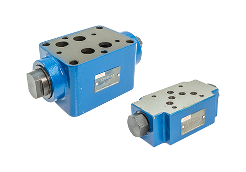
2025-12-19 There are significant differences between the superimposed hydraulic control check valve and the hydraulic lock in terms of function, structure, application scenarios and installation methods. The specific differences are as follows: 1. Functional positioning The core function of the superimposed hydraulic control check valve: adding a hydraulic control function to the one-way valve, allowing the oil to flow freely in the forward direction, and in the reverse direction, it can be actively opened by external control of oil pressure to achieve two-way flow. Additional functions: Hydraulic cylinder support: prevents the vertical hydraulic cylinder from sliding down due to slide valve leakage. Pressure maintenance: The tightness of the poppet valve is used to maintain pressure for a long time and make up for the gap leakage problem of the slide valve type reversing valve. Locking: When the reversing valve is in the neutral position, the hydraulic cylinder oil is sealed in both directions to prevent external force from moving the piston. Large flow oil discharge: When the hydraulic cylinder retreats, the oil pressure is controlled to open the hydraulic control check valve to avoid the throttling restriction of the small flow slide valve. Oil filling: When the vertical hydraulic cylinder descends at high speed, it acts as an oil filling valve to replenish oil to prevent air suction and negative pressure. Combined reversing: Two hydraulically controlled check valves are connected in parallel with the one-way valve to simulate three-position three-way reversing.
Read More 


