2026-02-07 Precautions for using the 4WE6 high-pressure solenoid reversing valve are as follows: Preparation before installation: Model verification: Before installation, the model and specifications of the solenoid valve need to be carefully checked to ensure that they are consistent with the system design requirements, including working pressure, flow, voltage and other parameters. Appearance inspection: Check whether there is any damage to the appearance of the solenoid valve, such as cracked shell, damaged coil, etc., to ensure that the solenoid valve is intact. Pipe cleaning: Clean the inside of the pipe connecting the solenoid valve to remove impurities, rust, welding slag and other foreign matter to prevent impurities from entering the solenoid valve and causing the valve core to jam or seal loosely. Installation location selection: Choose a dry, well-ventilated location that is convenient for operation and maintenance to install the solenoid valve. Avoid installing it in places with strong vibration, impact, or close to heat sources. Precautions during the installation process: Installation direction: Install strictly according to the fluid flow direction marked on the solenoid valve shell, ensuring that the medium flows in from the inlet end and flows out from the outlet end. Wrong installation direction may cause the solenoid valve to fail.
Read More 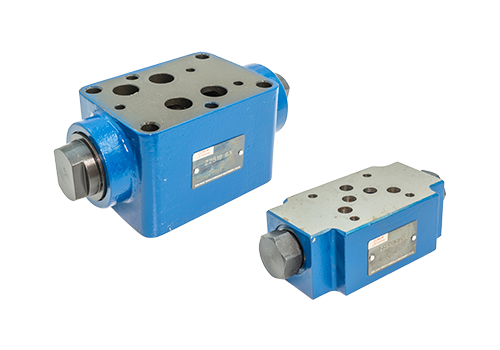
2026-01-29 The installation sequence and key points of the superimposed hydraulic control check valve are as follows: 1. Installation sequence The hydraulic control check valve installed on the bottom layer must be used as the bottom valve body and installed close to the foundation plate. This is to ensure the normal pressure-holding function and prevent pressure-holding failure due to improper installation position. Stacking Sequence In hydraulic systems, the installation sequence of stacking valves usually follows functional requirements. The typical sequence is: basic base plate → hydraulic control check valve (bottom layer) → pressure reducing valve/pressure valve → directional valve (such as solenoid reversing valve) → flow valve (throttle valve, etc.) → actuator connecting plate. If the system includes an externally controlled pressure reducing valve and a one-way throttle valve, the one-way throttle valve must be located between the externally controlled pressure reducing valve and the hydraulic cylinder; if used together with a hydraulically controlled one-way valve, the hydraulically controlled one-way valve must be located between the externally controlled pressure reducing valve and the hydraulic cylinder. Alignment of oil holes Before installation, it is necessary to confirm that the position of the oil holes of the superimposed valve is correct, and align all screw mounting holes to ensure smooth oil passage. The bolts are fixed with grade 12.9 high strength
Read More 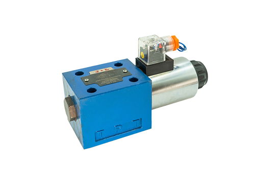
2026-01-26 Maintenance of single-head solenoid reversing valves requires daily inspections, regular cleaning, lubrication and maintenance, troubleshooting, installation specifications, environmental control, professional maintenance, etc. The specific methods are as follows: 1. Routine power supply inspection: Regularly check whether the power wiring is in good condition and ensure that the power supply voltage is within the working range of the solenoid reversing valve. If the power supply voltage is unstable or out of range, adjust or install a voltage stabilizing device in time. Appearance inspection: Check the appearance of the solenoid reversing valve for damage, deformation or leakage. If there is any abnormality, it should be dealt with or replaced in time. 2. Regular cleaning and internal cleaning: According to the usage conditions, regularly disassemble the solenoid reversing valve for internal cleaning. Remove impurities and dirt on the valve core, valve seat and other parts to ensure that the channels in the valve are unobstructed. External cleaning: Keep the outside of the solenoid reversing valve clean to prevent dust, oil and other impurities from entering the valve. Wipe the surface of the valve body with a clean cloth to keep it dry and clean. 3. Selection of lubricating oil for lubrication and maintenance
Read More 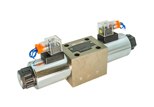
2026-01-24 The 4WE10 high-pressure solenoid directional valve has the characteristics of high pressure resistance, large flow processing, high-precision control, fast response, high reliability, flexible installation, energy saving and environmental protection, compact structure, adaptability to harsh environments and diversified functions. The following is a detailed introduction: High pressure resistance: The spool diameter of the 4WE10 series directional valve is larger and can withstand higher working pressure. Usually the rated pressure can reach 31.5MPa, and some models can withstand pressures up to 35MPa. They are suitable for high-pressure hydraulic systems. Large flow processing: This series of directional valves has a large working flow, with a flow rate of 120L/min to 320L/min, which can meet the needs of heavy-load machinery and equipment for large-flow hydraulic oil. High-precision control: Using advanced electromagnetic control technology and precise manufacturing technology, it can achieve high-precision flow and pressure control and ensure the stable operation of the hydraulic system. Quick response: The electromagnetic control system responds quickly and can quickly implement
Read More 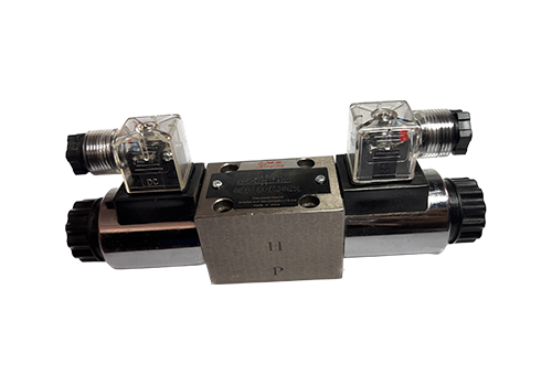
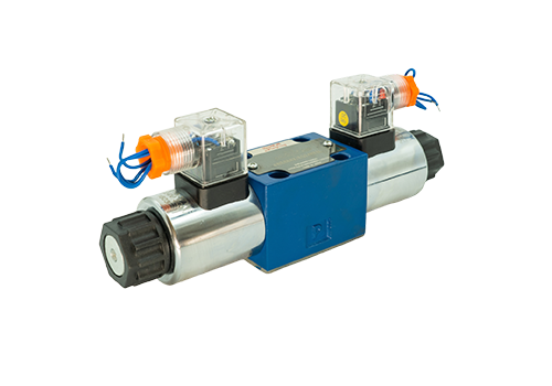
2026-01-22 As a key control component in industrial hydraulic systems, 4WE6 high-pressure solenoid directional valve has significant advantages such as high pressure and flow adaptability, fast response and long life, high compatibility and stability, flexible control method, structural optimization and convenient maintenance. The details are as follows: 1. High pressure and flow adaptability High rated working pressure: The rated working pressure of the 4WE6 series solenoid valve can reach 31.5MPa (some models are even higher, such as 350bar), which can easily meet the needs of high-pressure hydraulic systems. Wide flow range: The flow range is between 10-25L/min (there are slight differences in different specific models). The maximum flow capacity of some models can reach 80L/min, which meets the control requirements of large-flow hydraulic systems. 2. Fast response and long life. Fast response: the reversing time only takes tens of milliseconds, which enables the hydraulic actuator to move quickly, greatly improving the working efficiency of the system. use
Read More 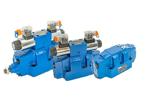
2026-01-19 The maintenance methods of 4WEH16 electro-hydraulic directional valve are as follows: Routine appearance and connection inspection: Check the valve body, valve cover, flange connection: Check whether there are signs of leakage, such as oil stains, water stains, rust spots, etc. If leakage is found, the connecting parts need to be tightened or the seals replaced in time. Observe the anti-corrosion layer on the surface of the valve: Check whether the anti-corrosion layer has fallen off. If it does, it should be repainted in time to prevent rust and corrosion of the valve body. Remove oil and dust from the valve surface: especially clean the valve stem and sealing parts to prevent impurities from invading the sealing surface and affecting the sealing performance. Can be wiped with a clean soft cloth or special detergent. Maintenance of the valve stem and transmission mechanism: Add designated grease: According to equipment requirements, add designated grease, such as lithium-based grease, high-temperature grease, etc., to the valve stem and transmission mechanism to avoid dry friction, reduce wear, and extend service life. Regular manual opening and closing: For normally open or normally closed 4WEH16 electro-hydraulic directional valve, regular manual opening and closing 1 - 2 times
Read More 


