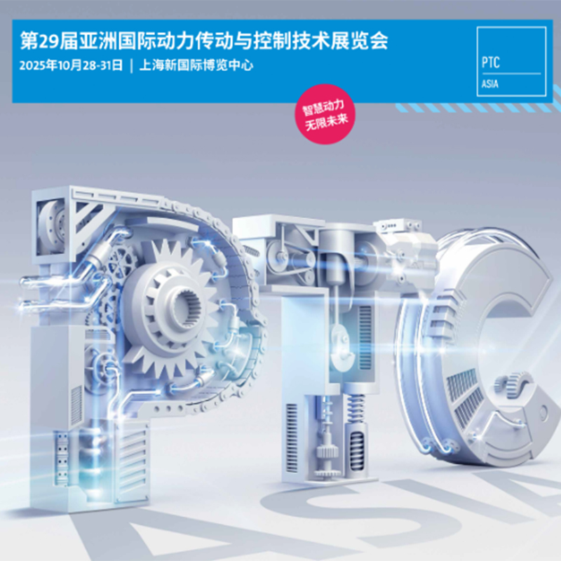
What are the characteristics of the 4WE10 single-head solenoid directional valve?
The characteristics of the 4WE10 single-head solenoid directional valve are as follows: heavy-duty design and high pressure resistance. The 4WE10 series adopts a heavy-duty design, with a larger valve core diameter, a working flow of up to 320L/min, a rated pressure of 31MPa, and a maximum pressure of 35MPa. It is suitable for heavy-duty machinery and equipment such as ships and injection molding machines. Its structure is standardized, durable and reliable, and complies with DIN24340 and ISO 4401 standards to ensure stable operation in high-pressure environments. Principle of combination of direct-acting and pilot-operated direct-acting: when the power is on, the electromagnetic coil generates electromagnetic force, which directly lifts the closing member to open the valve; when the power is off, the spring presses back the closing member to close the valve. It is suitable for small diameter, low pressure or vacuum conditions, with fast response speed, short action time and high opening and closing frequency. Pilot type: When the power is turned on, the electromagnetic force opens the pilot hole, forming a pressure difference to push the closing member of the main valve to move; when the power is turned off, the spring force or medium pressure pushes the closing member to reset. Suitable for high pressure difference or large flow scenarios
READ MOREFunction and adjustment method of superimposed relief valve
Stacked relief valve: full analysis of principles, adjustments and maintenance. As the core control component in the hydraulic system, the stacked relief valve assumes the important responsibility of stabilizing system pressure and ensuring the safe operation of equipment. With its unique structural design and flexible adjustment method, it has been widely used in industrial automation, construction machinery and other fields. This article will start from the basic concepts and systematically explain its adjustment methods and maintenance points to help readers deeply master this key technology. 1. The core characteristics of the stacked relief valve The stacked relief valve adopts a modular design concept and consists of a main valve core assembly and a stacked installation valve block. Its working principle is based on the pressure balance theory in fluid mechanics, and it controls the pressure and flow in the hydraulic system by adjusting the valve opening. When the system pressure exceeds the set value, the valve core automatically opens and leads excess hydraulic oil back to the tank to maintain system pressure stability. This design not only simplifies the hydraulic pipeline layout, but also realizes pressure control.
READ MOREWorking principle and characteristics of superimposed hydraulic control check valve
As a key component in the hydraulic system, the superimposed hydraulic control check valve has attracted much attention. The following is a detailed analysis of this hydraulic component: Working principle of superimposed hydraulic control check valve. Although the core working principle of superimposed hydraulic control check valve is similar to that of conventional hydraulic valves, it is the same in structural design and connection size, forming a standardized series. It not only has the control function of traditional hydraulic components, but also plays the role of oil passage. The layout of the main oil passage and bolt connection holes of each diameter series are consistent with the reversing valves of the same specifications, thus supporting flexible superposition and building a hydraulic control system with diverse functions. The valve is mainly composed of a solid steel valve body, one or two check valves, a pilot stage piston and a pilot cone valve spool embedded in the main valve spool of the check valve. When the oil flows from port A1 to port A2, the check valve (2) opens while pushing the pilot piston.
READ MOREWhat is the working principle of 4WEH16 electro-hydraulic reversing valve?
4WEH16 electro-hydraulic reversing valve is a combination device of an electromagnetic reversing valve and a hydraulically controlled reversing valve. The pilot oil circuit is controlled through the solenoid valve, and the main valve core is driven to move, realizing the switching of the direction of large flow liquid flow. Its working principle can be divided into the following steps: 1. The structure consists of a pilot solenoid valve: As a control unit, it is usually a two-position four-way or three-position four-way solenoid valve, and the valve core position is changed by energizing/disconnecting the solenoid. Main valve: Hydraulic reversing valve, with control chambers at both ends of the valve core, which pushes the valve core to move through pressure oil. Control oil circuit: includes two methods: internal oil supply (take oil from the main valve port P) and external oil supply (through independent oil circuit). The return oil is returned to the oil tank through the T port or the Y port. 2. Median state (both solenoids are powered off) Pilot valve state: The valve core is in the middle position under the action of the centering spring, cutting off the oil supply from the main valve control chamber. Main valve status: The pressure oil of the control chamber is returned to the oil tank through the T-port of the pilot valve, and the pressure at both ends of the main valve core is equal. Main valve core centering spring
READ MORE